Introduction
In this article, we take a look at the initial setup of a Palo Alto Networks firewall, including some very simple access rules and NAT and useful general settings.
Since I do not have a physical Palo Alto firewall to work with, I am going to set up a virtual Palo Alto firewall in VMware.
If you would like to set up your own Palo Alto firewall to play around with, you can apply for a VMware/KVM 30-day trial version here (requires a business email).
The PAN-OS version used in this lab is version 10.0.4. The firewall is being set up as self-managed, with no connection to Palo Alto's Panorama server.
Network Topology
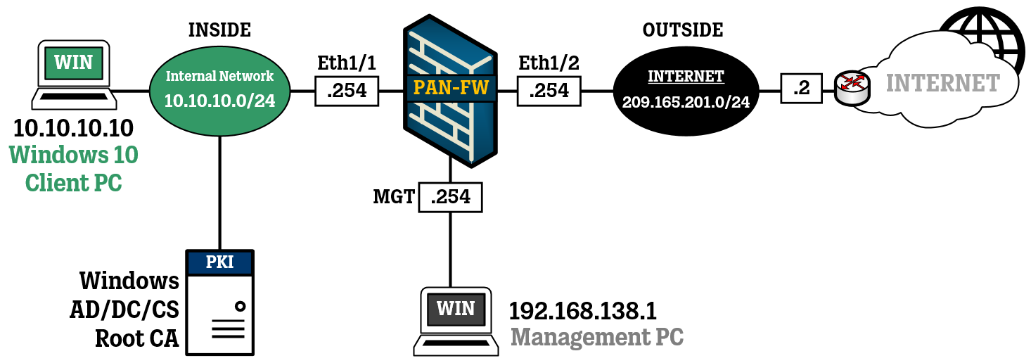
For this lab, the network topology is going to be very simple. I will set up a Palo Alto firewall and connect it to a PC for management. On the left side of the firewall there will be a Windows 10 client, and on the right side of the firewall is the connection to the internet.
To complete the topology shown above, I have set up the virtual Network Adapters in VMware to match the settings of my management station and my Windows 10 client.
Network Adapter #1 (unnumbered) = Management (MGT-port)
Network Adapter #2 = Windows 10 client network
Network Adapter #3 = connection to internet
This article will not be going through the details of spinning up a virtual device in VMware, you will have to look elsewhere for those steps.
Initial Setup (Management access)
Now that the VMware settings are done, we can start (power on) the firewall to go through the initial configuration steps to get the firewall up and running.
By default, the Management Port has an IP-address of 192.168.1.1 that can be accessed using a web browser. The Management Port has its own routing instance. However, based on my testing, if no connection is made to the Management port for some time, the firewall will turn on DHCP on the Management port in an attempt to get an IP-address for the administrator to connect to.
In my case, I will configure a static management IP-address using CLI and then connect to it using my web browser. The IP-address will be 192.168.138.254.
As someone not very familiar with Palo Alto firewalls at all, one thing I noticed after powering on the virtual machine, is that the CLI prompt changes throughout the bootup process and that we cannot immediately log in to the firewall. I do not know the purpose or differences of these CLI prompts, but they showed up in the order below and when I arrived at the PA-VM prompts, I could log in using admin/admin.
vm login: became PA-HDF login: after a failed login attempt and then became PA-VM login: after a minute or two passes, which is the prompt I was able to log in to.
After logging in with admin/admin, we are forced to change the admin password to something different. For some reason, even after changing the admin password, a message is displayed that the password must be changed (again), but there was no need to do that. Seems like it could be a cosmetic bug.
Go to the configuration mode using the command ”configure” (see how the prompt changes from admin@PA-VM> to admin@PA-VM# in the image below.
Next up, we turn off DHCP for the Management Port and instead set a static IP-address using the commands below. Along with the IP-address, a default gateway is configured (although not used for now) and a DNS-server (also not used for now).
set deviceconfig system type staticset deviceconfig system ip-address 192.168.138.254 netmask 255.255.255.0 default-gateway 192.168.138.1 dns-setting servers primary 8.8.8.8To activate the new configuration, use the command “commit”.
When the commit is complete, we can now access the web interface at IP-address 192.168.138.254.
Success!
After logging in, we arrive at the Dashboard, which shows system settings and general information about our firewall.
Configure General Settings
To complete our initial setup, there are some general settings left to be configured.
Head over to DEVICE > Setup > Management and click on the gear in the General Settings section.
Enter a proper hostname, domain, login banner and set the correct time.
Click on OK when you are done.
If you want to add more DNS servers, NTP-servers, or an HTTP Proxy for the firewall to use, you can add configure this by navigating to DEVICE > Setup > Services and clicking the gear in the Service section.
Since we have configured some new settings now, they need to be activated. To commit the changes to the configuration, click on the big Commit button in the top right of the web interface.
In the Commit window, you get the opportunity to review the changes that have been made by clicking on Preview Changes. The color-coding makes it very easy to see what has changed. In the image below, you can see that I added another DNS server to the firewalls configuration.
Close the preview window and click on Commit to activate your configuration.
After about half a minute or so, the Commit is complete!
Configure Security Zones
Up until now, we have mainly been working on settings related to the management and operations of the firewall itself. Now, we are going to configure some Security Zones, which can be used to configure access rules, after you have assigned some interfaces to them.
Security Zones in Palo Alto firewalls work very similar to zone concepts of other firewall brands. By assigning interfaces/networks to different Zones, one can make configuration clearer and easier to implement.
For our simple topology, we are going to create one zone called INSIDE and one called OUTSIDE. The interface connected to the Windows 10 client will be assigned the INSIDE zone and the interface connected to the Internet will be assigned the OUTSIDE zone, but more on that later.
Navigate to NETWORK > Zones and click on the +Add button in the bottom left corner.
Create two Zones with the names INSIDE and OUTSIDE, set the Type to Layer 3, and leave the rest of the settings blank, for now.
Don’t forget to repeat this step, create an OUTSIDE zone as well.
Configure Management Profiles
To allow certain network services (like ping) to be accepted on normal network interfaces, we need to create a Management Profile that permits these services, and then we attach this Management Profile to the network interfaces.
In this example, we are only going to allow ping, but you could allow actual management services on any normal networking interface (although you should probably limit the access to only IP-networks belonging to Network/Security Administrators.
Navigate to NETWORK > Network Profiles > Interface Mgmt
Click on the +Add button in the bottom left corner and create a new Management Profile that only allows the Ping service. Click on OK to finish.
Configure Network Interfaces
Now, it is time to finally configure the actual network interface of the firewall.
Head to NETWORK > Interfaces > Ethernet to see the interfaces available. In my case, we are going to use Ethernet1/1 for the interface facing the Windows 10 client on the Inside-network and Ethernet1/2 will be the interface that faces the internet.
Let's start with the configuration of Ethernet1/1.
Click on the Ethernet1/1 to get to the configuration window.
Assign a Comment to the interface (such as "Internal Networks"), set the Interface Type to Layer 3. In the Config tab, set the Virtual Router to "default" and set the Security Zone to the INSIDE zone we created earlier.
Continue to the IPv4 tab, select the Type called Static and use the +Add button to enter the IP address of this interface. In my case, this interface will use IP-address 10.10.10.254 with a /24 subnet mask.
Lastly, go to the Advanced tab. In the Other Info section, select the “PING-ONLY” Management Profile from earlier.
Click on OK when all the settings are done.
Next up, we configure interface Ethernet1/2 to face the internet.
Click on the Ethernet1/2 to get to the configuration window.
Assign a Comment to the interface (such as "Internet Access"), set the Interface Type to Layer 3. In the Config tab, set the Virtual Router to "default" and Security Zone to the OUTSIDE zone we created earlier.
We are not going to go into detail into what a Virtual Router implies in this scenario, just know that network interfaces need to belong to a Virtual Router to make use of a routing table and route lookups, be it static routes or via routing protocols.
Continue to the IPv4 tab, select the Type called Static and use the +Add button to enter the IP address of this interface. In my case, this interface will use IP-address 209.165.201.254 with a /24 subnet mask.
For security reasons, we will not assign a Management Profile to this interface, since I don't want it to be pingable from the internet.
Click on OK when all the settings are done.
Click on Commit in the top right corner to activate the new configuration.
After the Commit has been completed, your interface overview should look something like this:
Configure Routing
Now that we have the network interfaces in place, we can configure some form of routing. For this lab, the only routing that needs to be configured is a default route towards our ISP.
Navigate to NETWORK > Virtual Routers and click on the “default” Virtual Router. The default section is the Router Settings, in which you should be able to see both of your interfaces that belong to this Virtual Router (Ethernet1/1 and Ethernet1/2).
In the Static Routes section on the left side, click the +Add button and fill in the default route parameters, such as Destination 0.0.0.0/0, select interface Ethernet1/2 with a Next Hop IP-address of 209.165.201.2, which is the ISP's IP address.
Click on OK (and OK again) when you are done.
Click on Commit in the top right corner to activate the new configuration.
Security Policy
Next up, we need to configure a Security Policy to allow and deny traffic from passing through the firewall.
Navigate to POLICIES > Security to see an overview of the rule base of the firewall. In my firewall, there are two default rules: one rule that automatically allows traffic between interfaces attached to the same Zone, and one rule that denies traffic from interfaces attacked to different Zones from passing through.
In general, I personally do not like to rely on default rules, regardless of firewall brand, as such rules can change over time when upgrading or patching is performed.
By clicking the +Add button in the bottom left corner, I will add a new rule at the top called DENY ALL, and set it to deny from anyone (source IP/zone) to anyone (destination IP/Zone), for every application or service.
The configuration window for creating a rule is pretty straightforward: give the rule a name and then fill in the source/destination/application/service and set the Action.
Above the DENY ALL rule, we will create new rules of the traffic we actually want to allow to pass through the firewall.
I will create a few rules to allow ping, DNS (for the Windows 10 client to use Google's DNS at 8.8.8.8), and HTTP/HTTPS out towards the internet (the OUTSIDE zone).
To keep it simple, I will use the INSIDE and OUTSIDE zones as sources and destinations.
The Application parameter is used to determine the type of traffic is allowed to pass. The Service components can in general be left at "application-default" unless you need to use an obscure (non-standard) port for your communication.
For example, in one of my rules, I have added the Applications "web-browsing" and "ssl" with their Service set to "application-default". This will automatically open up ports TCP 80 (web-browsing) and TCP 443 (ssl) since those ports are in general associated with that type of traffic (application).
A rule to allow ping from the Windows 10 client (10.10.10.10) to its default gateway (the firewall's INSIDE interface at 10.10.10.254) is also added to the access rules.
Click on Commit in the top right corner to activate the new configuration.
Configure Network Address Translation (NAT/PAT)
For the Windows 10 client to connect to the internet, we need to configure Network Address Translation (NAT) to translate the device's internal IP address to an external IP address (like the one configured on our interface facing the internet).
Navigate to POLICIES > NAT and click on the +Add button to add a new NAT rule.
Create a rule, give it a name in the General tab, and then move on to the Original Packet tab.
Set up INSIDE as the Source Zone and OUTSIDE as the Destination Zone. To make this rule a bit more granular, I will also create a Network Object called Internal-Network-10.10.10.0 that represents the IP-network 10.10.10.0/24, which is used on the internal network where the Windows 10 client is located.
The last tab is the Translated Packet tab, in which you defined how the previously selected traffic is going to be translated. We will translate the internal network of 10.10.10.0/24 to the IP address of the firewall's internet-facing interface when traffic needs to go out to the internet.
Setting the Translation Type to ”Dynamic IP and Port” ensures that Port Address Translation (PAT) is being used, so we can hide many clients behind this one IP address, although in this lab I only have one Windows 10 client to test with.
When we are done, the NAT/PAT rule will look like this in the overview.
Click on Commit in the top right corner to activate the new configuration.
Testing and Verification
Following the last Commit, we are now able to confirm connectivity to the internet in different forms, as shown below. The Windows 10 client is able to do a DNS lookup using Google’s DNS 8.8.8.8, it can ping to Cloudflare’s famous 1.1.1.1 DNS server, and we are able to visit this very blog using a web browser.
We can also confirm that the Windows 10 client can ping to the internal interface of the firewall (which has IP address 10.10.10.254):
For a closer look at the logs of the traffic, navigate to MONITOR > Logs > Traffic to view the traffic in real-time as it arrives at the firewall and is allowed, or denied, based on the rules of our security policy.