Introduction
In this article, we are going to take a look at configuring a simple Site-to-Site VPN tunnel between two Check Point Security Gateways, managed by the same Security Management Server (”SMS”). On one side of the VPN tunnel will be an FTP server, and on the other side will be a typical client-PC that needs to access the FTP server.
The VPN tunnel will be set up as a Domain-Based VPN tunnel, which is often called Policy-Based VPN tunnel among other firewall brands. This article assumes you already have basic knowledge of how VPN tunnels work (IKE, IPsec, and so on).
Network Topology
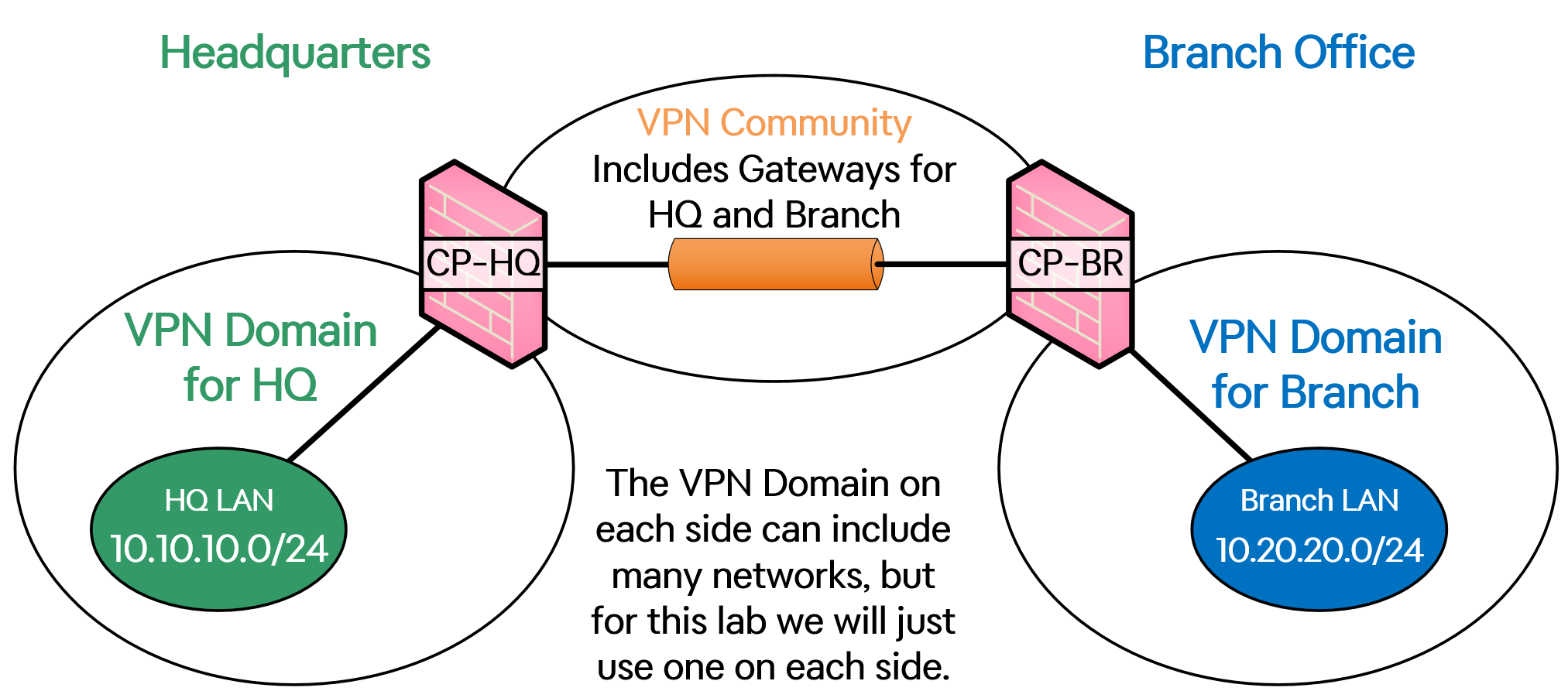
The network topology used to demonstrate can be seen in the image below.
On the left side we have an FTP-server connected to the headquarters Gateway called "CP-HQ", and on the right side with have the Branch Office's Gateway called "CP-BR", with a Windows 10 PC located behind it.
All Gateways are running version R80.40.
As for Security Policies, I am using two different policies for the Gateways, one for each, called POLICY-HQ and POLICY-BRANCH.
Because this is a lab environment, my SMS-server is directly connected to both Gateways using a separate network.
Let’s get into the configuration.
Activate IPSec VPN Blade on Gateways
Start by activating the IPSec VPN Blade on both your Gateways. Inside SmartDashboard, head to Gateways & Servers and double-click on your Gateways. On General Properties, go to the Network Security section and check the box for "IPSec VPN". Click OK to save and close the window.
Repeat this step for your other Gateway.
Do a Publish and Install Policy on both your Gateways.
Configure VPN Domains
Head back into each Gateways’ settings and navigate to Network Management > VPN Domain. By default, all networks that are considered internal to the Gateway will be allowed to traverse the VPN tunnel, but in my case, I am going to lock it down a bit by checking the "User defined" box and adding only the Network Object representing the LAN-side of each Gateway.
The object HQ-LAN-network represents IP-network 10.10.10.0/24 and we will add this to the VPN Domain of the Gateway “CP-HQ” (headquarters).
Click on OK to save your settings and repeat this step for your other Gateway as seen below.
The object Branch-LAN-network represents IP-network 10.20.20.0/24 and we will add this to the VPN Domain of the Gateway “CP-BR” (branch office).
Configure Link Selection
Once again, head back into each Gateway’s settings and navigate to IPSec VPN > Link Selection. This is where you can select which interface will be used as the source of the VPN tunnel. In R80.40, the default setting here is to use the "Main address", which is the IP address that the SMS server uses to connect to the Gateway.
Since the Main address for both my Gateways is the management IP address, I will have to change the Link Selection to use the IP address of my external interface (which resides in the 209.165.201.0-network).
Click on OK to save your settings and repeat this step for your other Gateway as seen below.
Click on OK to save your settings.
Publish and Install Policy on both your Gateways.
Choosing a VPN Community
The VPN Community is what decides which of your Gateways will be part of the VPN solution as a whole.
Two types of VPN Communities can be configured: Star or Meshed.
A Star VPN Community appoints one Gateway as the Star and the other gateways as Satellites, which are other terms for a Hub-and-Spoke network. In this type of topology, every Satellite Gateway has only one VPN tunnel destination, the Star Gateways, which acts as a “centerpiece” of all data that needs to go through the VPN tunnels. If data needs to be sent from the LAN of one Satellite Gateway to the LAN of another Satellite Gateway, this traffic will be passed through the Star Gateway first and then onwards towards the destination Satellite Gateway.
A Meshed VPN Community means that every Gateway that participates in the VPN Community will set up a VPN tunnel between them and EVERY other Gateway that is in the same VPN Community, creating a Mesh network of VPN tunnels. If you have a lot of Gateways, this will mean a lot of VPN tunnels will be created as well, and traffic is allowed to flow from any Gateway to any other Gateway directly.
Which type of VPN Community will fit your need is up to you to research, but for this lab, we will be going with the Meshed Community.
VPN Topology
To make some sense of what we are setting up, take a look at the VPN topology down below, which shows how all these terms come together.
Creating a VPN Community
To create a VPN Community, head to the Objects menu in the top right corner of SmartDashboard and click on New... More > VPN Community > Meshed Community...
A window will now pop up with a bunch of settings across different configuration sections (left side menu) and we will go through the sections one by one down below.
Gateways (Set a Community name)
In the first section, called Gateways, give the Meshed Community a Name and then add your Gateways as Participating Gateways using the plus (+) button. I will name my community LAB-MESH-VPN.
Encrypted Traffic
Continue to Encrypted Traffic, but DO NOT check the box titled “Accept all encrypted traffic”.
In my opinion, this checkbox is a huge red flag regarding security because it will make it possible for traffic to pass through the VPN tunnels without going through your Security Policies at all.
This checkbox essentially turns your Gateways into a router when it comes to handling the VPN traffic between your Gateways. While there might be some actual use for this feature, I would not feel comfortable using it broadly in production networks, unless a very specific use-case presents itself.
If you activate this feature and traffic passes through your VPN tunnels, it will still show up in the logs in SmartLog, but the Access Rule Number and Name columns will be empty, but you can see the automatically created Implied Rule that is created from this checkbox by going to one of your Security Policies > Actions > Implied Rules… as seen below.
ENCRYPTION
In the Encryption section, you can choose various settings related to IKE Phase 1 and IKE Phase 2 negotiations and what kind of protection the VPN tunnel will use when established.
In my case, I will set the community to only use IKEv2 (more secure than IKEv1) and then I will change some settings to give my VPN tunnels more secure settings than the default, all of which can be seen in the image below.
One of the good things about configuring a VPN tunnel between two Gateways that are managed by the same SMS-server is that the settings are applied to both, so you know there is no possibility of the settings being different on the Gateways, causing the VPN tunnel not to be established (which is more common than not when you are setting up VPN tunnels manually on each side).
For authentication between the Gateways, certificates will be used, but you will not have to worry about this because it is all handled by the SMS server automatically.
Tunnel Management
Next up is the Tunnel Management section, which has some interesting features for us. Here, you can configure the VPN tunnel to always be active, even if there is no actual traffic keeping the VPN tunnel up and running. This feature uses a Check Point proprietary protocol running on port UDP 18234 to send some kind of keep-alive packets through the VPN tunnel from time to time, according to Check Point's documentation.
There are a bunch of different options for selecting which tunnels to make permanent, but for this lab, I will select to make all the tunnels in the community permanent (which really isn't a lot in my case, since there are only two Gateways in my topology).
The other interesting setting in this section is VPN Tunnel Sharing, which determines how many VPN tunnels are set up between two Gateways, depending on what you select here. I am sure there are cons and pros with every selectable choice here, but I am going with the default choice, which is “One VPN Tunnel per subnet pair”.
There is probably some logic or best practice behind when each type of Tunnel Sharing option should be used depending on your network, but we will not go deeper into that here.
OTHER SETTINGS
There are some sections of settings that I will not cover because they are not important in my case or have rather specific use-cases not related to what we are trying to do in this lab, and I will instead now jump to the last section, which is the Advanced section.
ADVANCED SETTINGS
The “Disable NAT inside the VPN community” should be checked in most cases, as most VPN traffic tends to be directly IP-to-IP, without NAT involved. If you are setting up VPN tunnels towards a third party, you are probably more likely to run into having to use NAT to avoid IP conflicts, but that is not the case in this lab.
Click OK when you are done and then do a Publish and Install Policy on both your Gateways.
That’s all for the VPN Community settings.
Routing
Depending on your current settings, you might need to add routes to make sure the traffic to the other side of the VPN tunnel is sent out the external interface towards the internet, and not to some other routing point inside your internal network.
I will add the following routes to my Gateways using the Gaia CLI (“Clish”). You can also add these routes using the Gaia web-UI if you want to.
On “CP-HQ” (Gateway of the headquarters), we add a route for the 10.20.20.0/24-network out interface Eth2, which faces the internet:
On “CP-BR” (Gateway of the Branch Office), we add a route for the 10.10.10.0/24-network out interface Eth2, which faces the internet:
Configure Security Policy for VPN traffic
Now, it is time to create rules in the Security Policies of both Gateways to allow the traffic between the two LANs and to specify that this traffic is tied to the VPN Community.
Go to Security Policies, select your policy and create a rule that allows the needed traffic. In my case, I will permit the ICMP and FTP protocols. In terms of who is the source and who is the destination, this is always the same on both Gateways.
For example, if the Branch Office PC connects with FTP to the server in HQ, you will need an access rule both in the Branch Gateway and the HQ Gateways to allow this traffic, where the Branch PC (or its whole LAN) is the source and the HQ FTP-server (or its whole LAN) is the destination, and the Service is FTP with an Action of Accept.
For ease of use, Check Point's official documentation says you might as well put both sides of the VPN tunnel in both the destination and source columns to save yourself some headache.
Inside the column called VPN (which is a column you might have to add yourself by right-clicking on the blue column header at the top of the Security Policy and ticking the “VPN” box), right-click and click on “Specific VPN Communities...” to select the VPN Community we created earlier (“LAB-MESH-VPN” in my case).
All in all, the access rule will look something like this on the “CP-HQ” Gateway’s policy:
...and the rule will look exactly the same on the “CP-BR” Gateway’s policy:
Publish and Install Policy on both your Gateways!
Now you are done with the configuration and can start testing.
Verification
To test the VPN tunnel, I can use either a simple ping or FTP from the Branch Office PC to the FTP-server at HQ to trigger the VPN tunnel to be established between the two Gateways.
After a successful ping between the two, I can confirm that the Branch Office PC is able to connect with the FTP protocol to the FTP server in the headquarters.
...and the FTP-server software on the FTP-server shows that 10.20.20.10 has connected to it:
In the SmartLog, we can see that authentication between the Gateways takes place and the VPN tunnel is being set up. The IP addresses in this log look a bit strange due to how my management of the Gateways is set up, but you still get the idea.
As for the actual data traffic passing through the VPN tunnel, we can see encryption and decryption taking place on each Gateway when the Branch Office client PC connects with FTP to the FTP-server at HQ:
The detailed log shows a bit more information, like which encryption methods are being used:
To get into the nitty-gritty of VPN tunnels, use the command "vpn tu", which launches the VPN TunnelUtil function. This interactive function displays a list of options for you to choose from, each of which can show you more information about already established VPN tunnels or delete them, if you need to restart a VPN tunnel, for some reason.
Final Notes
The permanent tunnel setting we activated can be seen in the SmartLog, under the Service name "tunnel_test", although it seems that the source and destination IP-addresses in my case are the management IP-addresses of my Gateways, which wouldn't really work as a keep-alive through the VPN tunnel, but it might just be a cosmetic error due to my setup of the Gateways’ management network.