In this article, we take a look at how to configure High Availability Stateful Switchover (HA SSO) on the Cisco 9800 WLCs running IOS-XE using Redundancy Management Interfaces (RMI) in addition to the Redundancy Ports (RP).
Introduction
Running WLCs in a High Availability Stateful Switchover setup is a must for any critical network, as the WLC is such a central part of modern wireless networks. Stateful Switchover ensures that no user impact occurs in the event of a failover, and the WLCs themselves can be configured in multiple ways to keep in touch with the respective partner WLC, ready to take over at any time.
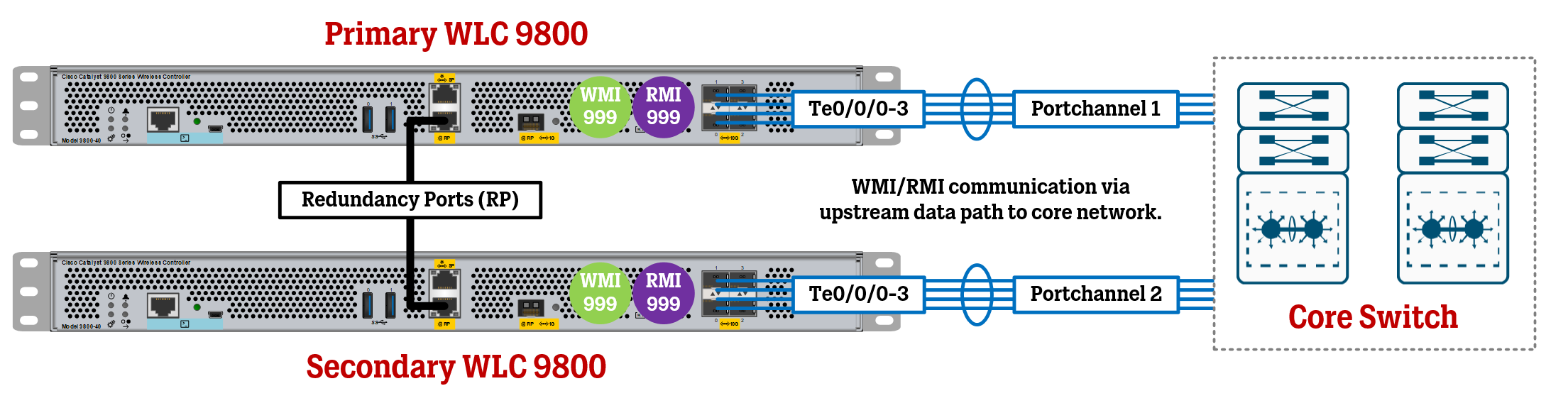
The purpose of this article is to go through the configuration of physical WLC 9800 High Availability using Redundancy Management Interfaces, or RMI (which acts as an additional set of IP addresses configured in each WLC for monitoring and heartbeat purposes between the two, mainly via the upstream data path of the network), and the physical Redundancy Port, which connects the two WLCs back-to-back for synching configuration and states, in addition to running monitoring and heartbeat service, as well.
Pre-requisites
The two WLCs must be of the same model.
The two WLCs must be running the same software version.
The configuration below assumes you are configuring two WLCs from factory default settings. If you are configuring WLCs that are already live in a production network, you may need to perform other steps to not disrupt your network environment. Plan accordingly!
Reserve 4 IP addresses in a management VLAN to be used for the WLCs. Two of the IP addresses will be used for the WLCs’ Wireless Management Interfaces (WMI), while the other two IP addresses will simply be used for redundancy monitoring via the virtual Redundancy Management Interfaces (RMI).
IP addressing for the Redundancy Ports will be automatically generated, based on the IP addresses used for the RMI. The IP addresses used will be 169.254.X.X where X is the last two octets of the RMI IP address of each WLC.
Make sure your planned final topology is supported by Cisco, check out official documentation to make sure your physical connections between the WLCs and the rest of the network
As for IP addressing, we will go with the following:
Primary WLC Wireless Management Interface (WMI) IP Address = 10.10.99.10
Secondary WLC Wireless Management Interface (WMI) IP Address = 10.10.99.11
Primary WLC Redundancy Management Interface (RMI) IP Address = 10.10.99.12
Secondary WLC Redundancy Management Interface (RMI) IP Address = 10.10.99.13
This means that the very first IP address 10.10.99.11 is the IP address that you, the administrator, will connect to using HTTPS/SSH to manage the HA pair once the configuration is in place.
The Core Switch to which the WLCs will connect to has IP address 10.10.99.1 on VLAN 999.
As previously explained, the IP addresses for the physical Redundancy Ports will be based on each WLC’s RMI IP address. The end-result of this is that the Redundancy Port IP address of the Primary WLC will be 169.254.99.12, with the Secondary WLC’s being 169.254.99.13.
Primary WLC Configuration
First, we will configure the Primary WLC. We will need to configure a Management VLAN (VLAN 999 in this case) to then assign the Wireless Management Interface (WMI) IP address and Redundancy Management Interface (RMI) IP address (configured as a secondary IP on the same VLAN.
*! Do note that Cisco recommends that you use different VLAN(s) for connecting the Access Points themselves if your deployment has more than 100 Access Points:
* vlan 999
name WLC-MGMT
! Create VLAN interface for Wireless Management Interface (WMI) and Redundacy Management Interface (RMI):
interface vlan 999
description WLC-MGMT
ip address 10.10.99.10 255.255.255.0
ip address 10.10.99.12 255.255.255.0 secondary
no shutdown
! Designate VLAN as Management VLAN:
wireless management interface Vlan999
! Configure Default Route
ip route 0.0.0.0 0.0.0.0 10.10.99.1 name DEFAULT-ROUTE
! Configure physical interfaces (preferably using LACP Port-Channel):
interface range
Te0/0/0-3
description
Trunk Upstream Core
channel-group
1 mode active
interface portchannel 1
description Trunk Upstream Core
switchport mode trunk
switchport trunk allowed vlan all
no shutdown
! For Primary WLC, set priority to 2 (highest priority):
! Note that this command is configured in Privilege EXEC Mode (WLC# prompt)
chassis 1 priority 2
! Enable HA SSO mode:
config terminal
redundancy
mode sso
! Designate Management VLAN as Redundancy Management Interface (RMI):
redun-management interface Vlan999 chassis 1 address 10.10.99.12 chassis 2 address 10.10.99.13
! Save configuration:
do write mem
Secondary WLC Configuration
Next up, we will configure the Secondary WLC. Most of the configuration is very similar to the Primary WLC, except for the IP addresses and the fact that we need to make this unit the Secondary Unit.
vlan 999
name WLC-MGMT
! Create Wireless Management Interface (WMI) and Redundacy Management Interface (RMI):
interface vlan 999
description WLC-MGMT
ip address 10.10.99.11 255.255.255.0
ip address 10.10.99.13 255.255.255.0 secondary
no shutdown
! Designate VLAN as Management VLAN:
wireless management interface Vlan999
! Configure Default Route
ip route 0.0.0.0 0.0.0.0 10.10.99.1 name DEFAULT-ROUTE
! Configure physical interfaces (preferably using LACP Port-Channel):
interface range
Te0/0/0-3
description
Trunk Upstream Core
channel-group
1 mode active
interface portchannel 1
description Trunk Upstream Core
switchport mode trunk
switchport trunk allowed vlan all
no shutdown
! For Secondary WLC, renumber this unit ("chassis") to number 2 (but let priority stay at 1, which is default):
! Note that this command is configured in Privilege EXEC Mode (WLC# prompt)
chassis 1 renumber 2
! Enable HA SSO mode:
config terminal
redundancy
mode sso
! Designate Management VLAN as Redundancy Management Interface (RMI):
redun-management interface Vlan999 chassis 1 address 10.10.99.12 chassis 2 address 10.10.99.13
! Save configuration:
do write mem
Configure Trunk/Portchannel on Upstream Core Switch
Do note that while Port-channel 1 was used on both the Primary and Secondary WLC above, on the upstream core switch these need to be different.
For example, use Port-channel 1 for the physical ports that will connect to the Primary WLC, and use Port-channel 2 for the physical ports that will connect to the Secondary WLC.
! Configure Port-channel to Primary WLC (WLC01):
interface range Te1/1/1-4
description Trunk Primary WLC01
channel-group 1 mode active
no shutdown
interface Portchannel 1
description Trunk Primary WLC01 Portchannel
switchport mode trunk
spanning-tree portfast trunk
no shutdown
! Configure Port-channel to Secondary WLC (WLC02):
interface range Te2/1/1-4
description Trunk Secondary WLC02
channel-group 2 mode active
no shutdown
interface Portchannel 2
description Trunk Secondary WLC02 Portchannel
switchport mode trunk
spanning-tree portfast trunk
no shutdown
do write mem
Connect WLCs to each other and the rest of the network
With all the configuration in place, it is now time to connect the WLCs to each other using the Redundancy Ports (either directly or via a dedicated VLAN in your core switch or similar) and to the rest of the network using the data ports (physical ports/port channels).
Make sure you have saved the configuration on both WLCs, then issue the “reload” command and while the WLCs are reloading, connect all of the cabling.
If the WLCs are going to be positioned far apart from each other (different data centers), I would suggest building a temporary testing network “offline” that matches your production network, which will help you confirm that the HA configuration is successful before the WLCs are connected to the production network.
To do this, all you need is a single switch with the management VLAN and the IP address of the default gateway (10.10.99.1 in my case) so that the WLCs can confirm it is reachable.
After the HA cluster is up and running, there are some optional useful features to enable, down below.
Post-configuration Tasks
Enable Gateway Monitoring, allowing the WLCs to keep track of their Default Gateway and allowing for failover if something were to happen to the path to the default gateway for the currently Active WLC.
management gateway-failover enable
Enable the Console port on the Standby WLC, this may be useful for general troubleshooting.
redundancy
main-cpu
standby console enable
Verification
Use the command “show chassis” to quickly see if the WLCs are synced up with each other (Current State is “Ready”) and which IP addresses have been automatically assigned to the Redundancy Ports.
Use the command “show redundancy states” to see some general settings of the current Active WLC and to see if additional features like Gateway Monitoring are enabled.
Force Failover to Test Redundancy
If you want test the redundancy by forcing a failover, you can either unplug the Primary WLC (which should currently be the Active WLC) or you can use the command below:
redundancy force-switchover
References
BRKEWN-2846 - High Availability Design with Cisco Catalyst 9800 Wireless Controllers